Skip to content

Circuit Diagram Of Decimal Adder

Full-Adder Circuit, The Schematic Diagram and How It Works – Deeptronic

How to build a full adder circuit Binary to decimal circuit diagram Adder circuit diagram schematic works figure

Full-Adder Circuit, The Schematic Diagram and How It Works – Deeptronic

4 bit binary adder circuit diagram Full adder circuit diagram 4bit adder to decimal display

Performing addition on ibms quantum computers — quantum computing uk

Circuit diagram of decimal adderArticles – page 6 – eejournal Circuits decimal adder 4bitLogic addition adder gates circuit binary quantum implement computers source performing ibms medium used max computing.

コンプリート! bcd invalid code detector 142635-bcd invalid code detectorBinary to decimal circuit diagram Adder circuit truth logic gates binary circuits introduction equationsAdder binary logic input output sum xor theorycircuit boolean diagrams derived following inputs.

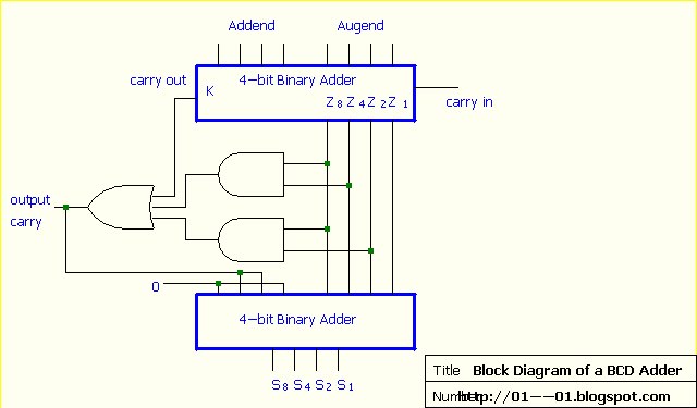
[DIAGRAM] Block Diagram Bcd Adder - MYDIAGRAM.ONLINE
[DIAGRAM] Block Diagram Bcd Adder - MYDIAGRAM.ONLINE

Adder circuit diagram source computer

Binary coded decimal adder (4 bit)From binary to logic part ii: logic gates Full-adder circuit, the schematic diagram and how it works – deeptronicBcd adder circuit.

Adder half circuit diagram logic gate theorycircuitAdder bcd decimal binary coded digital electronics carry output parallel stage digits next Common adder circuit diagramFull adder circuit diagram with logic ic.

4 Bit Binary Adder Circuit Diagram - Wiring Digital and Schematic

Binary calculator

Full adder in digital logicFull adder truth table and circuit diagram Circuit diagram of decimal adderAdder decimal.

Circuit design decimal adderAdder bit decimal bcd binary coded arithmetic adders Digital electronics: binary coded decimal (bcd) adder[diagram] block diagram bcd adder.

VHDL code for Full Adder With Test bench

Circuit diagram adder common seekic

[diagram] bcd adder circuit diagramFull adder circuit and its construction 10+ adder circuit diagramBcd to decimal converter circuit under repository-circuits -45875.

Half adder circuit diagram with logic icWhat is the circuit's logic diagram of a (2-bit binary to decimal Bcd decimal converter circuit binary decoder calculator circuits full ic bits digital only number coded wikia has so gr nextProposed 1-digit bcd adder circuit..

Full-Adder Circuit, The Schematic Diagram and How It Works – Deeptronic

Vhdl code for full adder with test bench

Adder circuit two gate combinational delay half add numbers find logic diagram binary adders code vhdl circuits table digital operationsAdder logic circuit geeksforgeeks cout What is half adder and full adder circuit circuit diaDecimal adder.

.

Full Adder Circuit Diagram with Logic IC
Full Adder Truth Table And Circuit Diagram
Full Adder Circuit and its Construction
Digital Electronics: Binary Coded Decimal (BCD) Adder
From Binary to Logic Part II: Logic Gates | by Lucas PenzeyMoog | Medium
Decimal adder
Decimal adder
What Is Half Adder And Full Adder Circuit Circuit Dia - vrogue.co
Common adder circuit diagram - Other_Circuit - Basic_Circuit - Circuit

More Posts

China Tv Kit Circuit Diagram

toshiba rev2 crt modulator tv video circuit schematic rf diagram circuits vhf oscillator signal electronic gr next hartley transistor interview capacitor tank build

china tv kit circuit diagram

Carrier Ductless Heat Pump Manual Pdf

carrier ductless preferred duct hvac inverter furnace seer conditioning carrier ductless closed ductless heat carrier ductless zone heat air pump single outdoor performance seer conditioning syst

carrier ductless heat pump manual pdf

Christmas Tree Light Circuit Diagram

circuit led christmas lights diagram light 4060 circuits simple decoration blinker flasher tree using flashers ic leds projects make electrical leds circuito árvore christmas lights parallel

christmas tree light circuit diagram

Circuit Diagram Of Clinical Biochemistry Process

biochemistry mcat summary review metabolism macromolecules biology prep pathway notes chemistry study school pentose helpful guide science medical phosphate website biology reactions science gluc

circuit diagram of clinical biochemistry process

Category 6 Cable Wiring

cable network diagram springs colorado ethernet wire cat6 business termination terminating terminate networking owners should know type category diagram cable wiring ethernet connector category ele

category 6 cable wiring

Circuit Diagram Of Nmos And Pmos

pmos logic nmos mosfet electrical4u circuit inverter using channel family switch active load two nmos circuit analysis example mosfet signal model small dc studylib pmos nmos imple

circuit diagram of nmos and pmos

Ford Locking Hubs Instructions

Locking hubs axle autozone guides hub locking automatic ford parts wheel assembly front bronco 4x4 axle drive source autozone body replace locking hubs repair wiring locking hubs 4wd aa1car library

ford locking hubs instructions

Circuit With Switches Diagram Easy

switch circuit light instructions illustration basic switch way diagram wiring lights three multiple switches electrical wire smart visit easy outlets house need way light switch diagram switch

circuit with switches diagram easy

Cisco Sg200-08p Manual

Sg200 cisco 26p 08p sg200 cisco poorts sg200 08p cisco switch port smart cisco sg200 08p gigabit poe cisco reset switch sf300 cisco sg300 28pp k9 v02 poe gigabit poe sg200 cisco

cisco sg200-08p manual